As a fun project and a way to get familiar with the popular Raspberry Pi platform, our team decided to build a real life display that can hang on the wall and be used to display various team metrics such as pageload speeds, burndown progress, achievement counts, etc. Below you will find a tutorial on how to make your own display as well as a link to all the code used to run the project.
We chose this project because microcontrollers can be a fun way to break out of the day to day programming patterns in web or systems projects. The real strength of working with microcontrollers is that the output can be in physical objects instead of on screen. This opens up quite a different world of possibilities and allows you to make very large displays without the cost of a large LCD Screen. Our hope is that this project may get people interested enough in microcontrollers to make their own supersized display.
Parts List
We used a Raspberry Pi 3 for this project. We also used a high torque servo that can be found here:
https://www.adafruit.com/product/1142
You will need 2 power supplies. One for the Pi and one for the servo. I would recommend going above 1.5 amps on a 5v supply for the servo
https://www.adafruit.com/product/1995
Additional male/female header wires can be found on Adafruit.
Overview
The general architecture of the display is a Raspberry Pi receiving values via web requests and then translating those values into signals for a motor which controls the display. The Pi runs 2 programs in order to accomplish this task. One is a Node.js program to receive the values and store them in local memory. The other is a Python program which calibrates the motor, grabs the value from the Node.js server, then turns the arrow on the display.
Software Challenges Faced
The main software challenges faced in the project were learning how to run a Node.js Server off of a Raspberry Pi, and communicating with the servo motor without a dedicated microcontroller shield.
Setting up Node.js Server
Luckily installing and starting a Node.js server on a Raspberry Pi is a pretty straightforward process. Our Raspberry Pi 3 came with Node.js pre installed. If Node.js is not found on your system, you can install with the following command.
In our file ‘set_value_server.js’ you can see the code we use to store and retrieve the display value via web requests. After setting up a basic Node.js server, we also include the set_value function to parse through web requests. This function parses the incoming web requests to identify the ‘position’ parameter. If this parameter is found, then our global value is set and returned to all future requests.
Controlling the Motor with Python:
I should start by saying our understanding of Pi communications with the motor were based heavily off of this tutorial from Adafruit. https://learn.adafruit.com/adafruits-raspberry-pi-lesson-8-using-a-servo-motor/software
In short, the open source WiringPi library offers access to the Pi’s pins to control electrical read and writes. By using the Pi’s internal pulse width modulation capabilities we can output a repeating electrical signal at various speeds which the motor then translates to specific positions. Installing the WiringPi library is a bit tricky on the Pi. The following commands must be run in this order:
The wiring table found here is also very helpful for using WiringPi. https://projects.drogon.net/raspberry-pi/wiringpi/pins/
In our ‘motor_control.py’ file you can see we start off with some boilerplate code to configure the Pi to communicate with our servo motor.
In these lines of code, we are directly setting the range for our motor’s electrical signals.
Every servo motor is slightly unique and the range of pulses that move the motor all the way from its maximum right and left turning angles will be unique. If you reset these values and then run the python program, you can see if this is the correct range for your motor. The first thing the program does is tells the motor to try the minimum and maximum values so that the motor can be calibrated. That code is below.
Finally at the bottom of the program code, we can see that an endless loop is set up to check our set_value server and then move the motor with the wiringpi.pwmWrite(18, int(pulse_amount)) command.
Setting up Hardware:
The circuit needed for this hardware is actually very simple since there is only one outside component. The diagram below was made with the excellent open source program Fritzing.
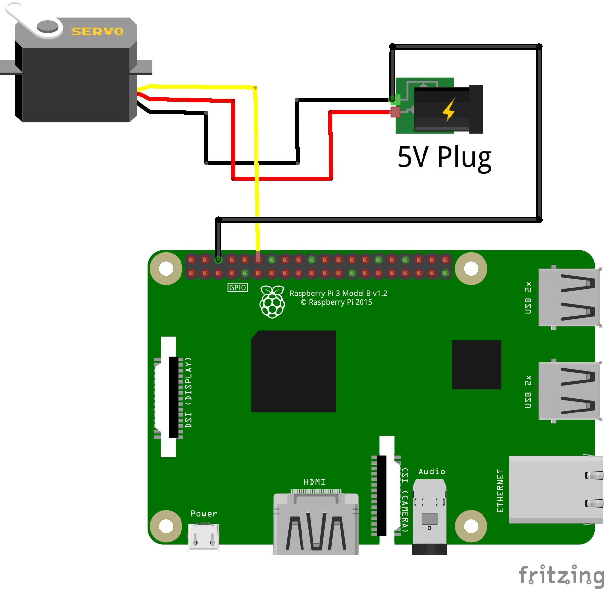
The power and ground from the servo are connected to the 5v plug’s power and ground. For the power supply to the motor, you will need to strip off the mini usb header and connect the wires directly to the motor. Be very careful that the ground and neutral wires do not ever touch, as this will cause a short and sparking.
The servo’s control wire is connected to the Raspberry Pi’s pin 12. Additionally the common ground wire needs to be connected from the Pi’s pin 6 to the plug’s ground. The circuit will not work without the common ground connection.
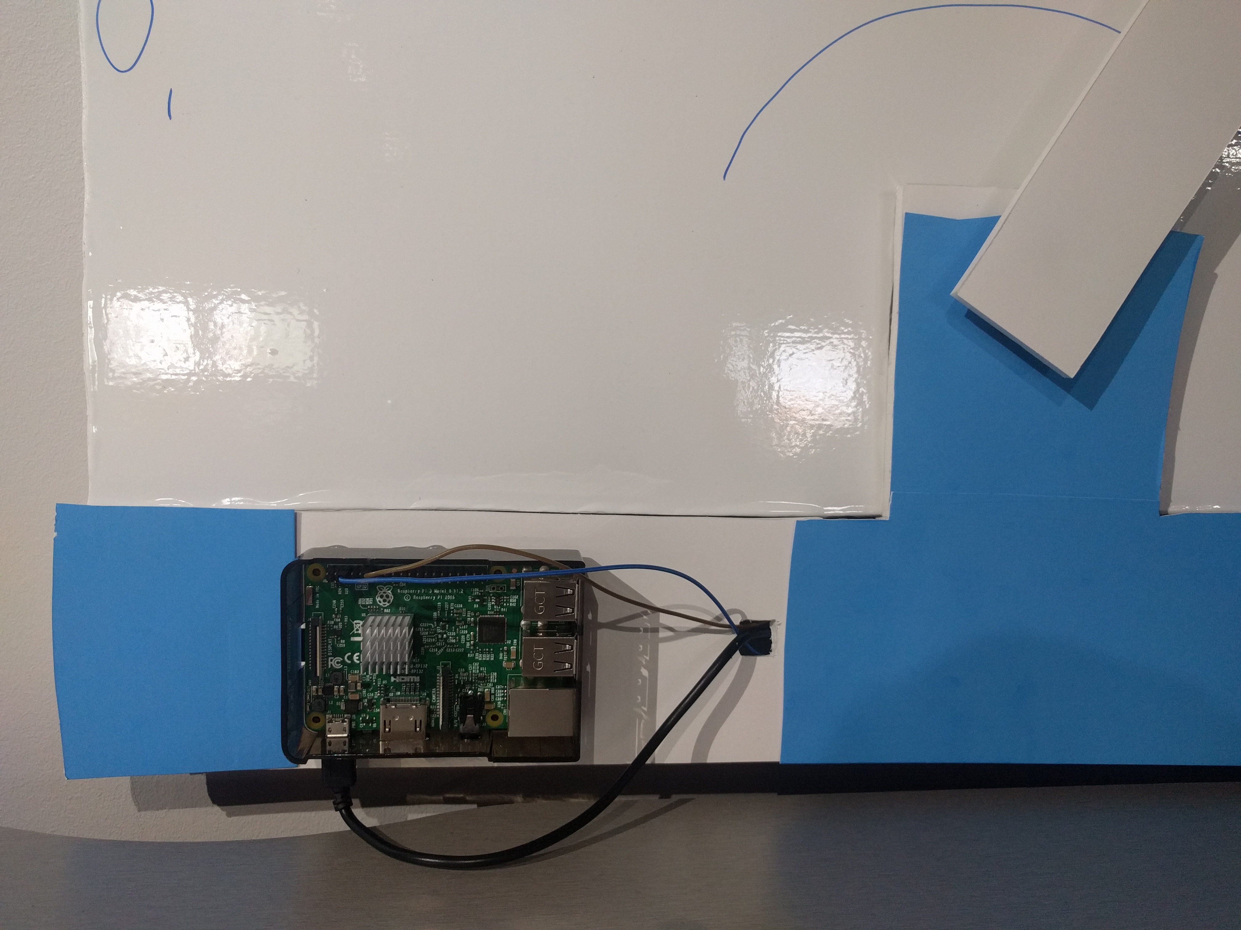
Construction:
Using the Display:
You can get all of our code onto the raspberry pi by cloning our github repository from your Pi. All the code is also available at the bottom of this blog post. Starting the programs once installed onto the Pi is very simple. Open a terminal and navigate to the folder containing the programs. Then run the command:
This is a very short script which starts the Node.js and Python programs together.
After both programs have been started, you should see your motor attempt to calibrate all the way left and right. Once this has finished the display is ready to receive inputs.
To communicate with the Pi you will need to identify its local IP address. Here is a short tutorial for that, https://learn.adafruit.com/adafruits-raspberry-pi-lesson-3-network-setup/finding-your-pis-ip-address.
This also works well if you know the Pi is online. You can run from any computer on your network without ssh’ing into the Pi.
With IP address in hand, you can now start moving the arrow on your display. On any computer connected to the same network as the Pi, open a web browser and navigate the the url
where IP_ADDRESS is the ip address of your Pi and VALUE is a value from 0-100.
Conclusion
This project’s scope changed several times during the course of its development, much like all side projects. The biggest change was to configure the ‘set_value_server.js’ program to accept agnostic values between 1 – 100. We added this feature so that any program can be hooked into the display as long as it outputs a number from 1 – 100. It is our hope that the team here at Element 84 can get creative with what metrics are displayed on a day to day basis. (We’ve already had some highly technical suggestions like “counting cups of coffee” and “days until the weekend”)
Overall this was a very fun project. When you are immersed in any type of programming it can be refreshing to take a break and see what another style is like. Along the way we learned a lot about the Raspberry Pi ecosystem, and set ourselves up for the next Raspberry Pi project in the future. Hope you enjoyed the tutorial and feel free to reach out if you get stuck while building your own Pi project.